Other Designs
Barrels Design
Clover Leaf
Ellipsoidal Design
Ellipsoidal Modules
On Three Levels
Pentagonal Ring
Hexagonal Ring
6-segment Anulus
Torus Dwelling
Twin Daisy Dwelling
Yin-Yang Design
Multi-Petal Designs
Other Designs
This was the second of my early conceptual designs. With this, I went into much more detail and produced what could well have been a very desirable place in which to live and work.
My first vision of a fantasy dwelling comprised two ellipsoidal 9-room units shaped a bit like 'flying saucers' — a bit like a pair of ellipsoidal chocolate buttons. The living space in each unit was arranged in the form of 8 circular rooms surrounding a single larger circle. Each room featured a central round skylight. The details of its form and structure are shown below.
| KG = Kitchen Garden | Patio = decorative pebble patio | |
| PG = Patio Garden | Patio = decorative pebble patio | |
| Hers = Her private space | Hers = her private room | |
| DK = Diningroom/Kitchen | BED = Main bedroom | |
| LA = Lounge/Auditorium | His = his private room | |
| TD = Twin Den | EC = Entrance Hall/Cloakroom | |
| EC = Entrance Hall/Cloakroom | Laun = Laundry room | |
| His = His private space | Bath = Bath Room | |
| WT = Washroom/Toilet | Wash = Wash Basin & Toilet |
Two of the circles form a bounded outside area for a kitchen garden and patio. This area is open to the outside because an elliptical section of the roof above it has been omitted. The kitchen garden contains herbs and flowers. It has a small retractable staircase to the outside ground level. The patio has a central fire grating where people can sit and chat round a wood fire Red-Indian style.
The dining room/kitchen has a central round dining table under a central sky light. Around the outside of this larger circular room is inset all the appliances, cupboards and work surfaces of a normal kitchen.
The lounge/auditorium has a large viewing screen and a good sound system. It has comfortable seating arranged around half of the circle for convenient viewing of the screen. There is also a central low table reachable from all the seats.
The entrance/cloakroom has access to the lounge/auditorium, dining room/kitchen and toilet/washroom. Access to the outside is via a short retractable staircase.
The twin den is a place where the couple who live here pursue their intellectual and practical hobbies and necessities, and is equipped accordingly. The twin den is flanked on either side by private rooms — one for him and one for her.
The central bedroom is dominated by a 2 metre square dohyo-bed with a feather-filled mattress. The dohyo-bed is set in the very centre of the bedroom with its foot facing the double patio through large floor to ceiling windows. At the head of the dohyo-bed is a small table. The bed is the sole feature of this minimalist-style bedroom. Its large square shape is more than adequate for facilitating all possible forms of love-making and repose.
Beyond the head of the bed is a door to the double bathroom. One half of this contains a central round bath with cupboards for towels and other bathroom requisites around its periphery. The other half of this double bathroom contains a wash basin, toilet and shower — again with generous cupboard space built into its circular wall.
Adjacent to the double bathroom is a private room, one for each member of the couple. His or her private room is for that individual's clothes and personal things. It is also a place to which each may retreat to be alone sometimes.
On one side of the patio is the laundry room which contains all the appliances and storage needed to wash, dry, air, iron and repair clothes. On the other side is the entrance/cloakroom which is a buffer between the bedroom and the outside and has clothing cupboards built into its circular wall.
The relative positions of the functional spaces within each module is completely flexible. Below is a slightly different arrangement, which I did for a tropical location.
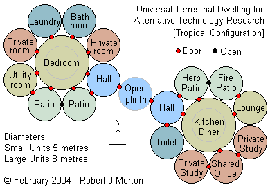
The shape of the modules also remains flexible. For example, modules could be cylindrical, ellipsoidal or they could be conical like a tepee. I would prefer them to be made of local natural materials like wood, but I do not want to shun modern materials like metal, fibreglass, glass and plastic provided they are durable in the very long term, thus justifying ecologically the energy used to extract and form them.
Each envelope is formed as a moulded wooden ribbing framework clad with aluminium or weatherproof plastic with a matt silvery or golden finish, or alternatively coloured to blend with its surrounding environment. Its floor level is half a storey above ground level — about 7 average stairs. It could however be raised to a full storey above the ground in order to provide useful shelter beneath it such as for parking a vehicle.
Perhaps an easier way is to pre-fabricate the construction making each room a separate ellipsoidal unit that interlocks with its neighbours to form the composite daytime or night-time superunit that looks a bit like a daisy, as shown here:
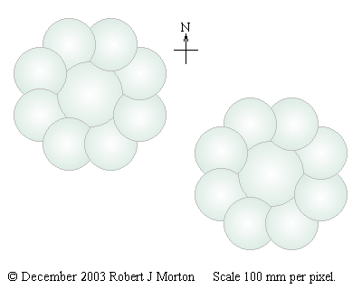
This design is for a dwelling for a lone couple. However, a third module may be added containing bedrooms and other necessary facilities for the couple's children and for visitors.
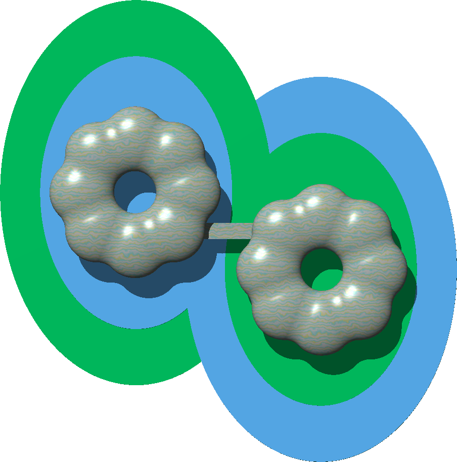 I think it is important for health and inspiration to set the dwelling in beautiful surroundings. There must be many possibilities, but I had, at that time, a design that was a particular favourite.
The daytime half of the dwelling is set on an elliptical island 24 by 34 metres, which is, in turn set centrally within an elliptical lake measuring 34 by 48 metres. The night-time half is set on 1 metre stilts in a 24 by 34 metre elliptical lake ½ metre deep, and which in turn is set centrally within a 34 by 48 metre elliptical garden.
At the south (bottom) end of the island are two buried units. One is a large electric battery. The other is a biological septic tank for processing sewage. The area of the lake (including the island) is about 1900m².
Following are my technical notes on how I would set about constructing the lake shown in the diagram below.
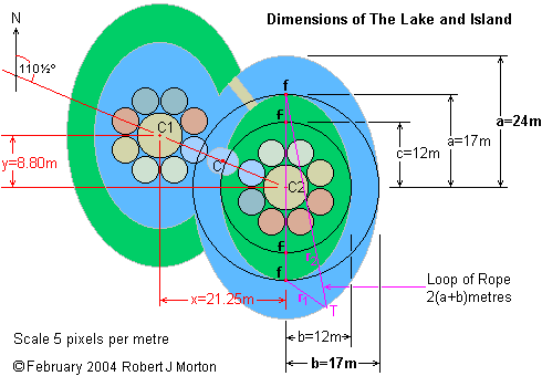
| Definitions | Relationships |
|---|---|
| a = semi-major diameter | r1 + r2 = 2a |
| b = semi-minor diameter | a² = b² + c² |
| c = distance between the centre and one of the foci | area of ellipse = πab |
| r1 = distance from one focus to the circumferance | |
| r2 = distance from other focus to the circumferance |
Large ellipse: a = 24 metres, b = 17 metres, c = 17 metres, area = 1282 m²
Small Ellipse: a = 17 metres, b = 12 metres, c = 12 metres, area = 641 m²
Observation: for an ellipse where a = b times the square root of 2, b = c
Calculating the length of the perimeter of an ellipse is very complicated, even more so, the calculation of the length of part of its perimeter. However, we know that its perimeter is somewhere between the circumference of the circle of radius a and the circumference of the circle of radius b. Let's assume it's just over half way between them. So the perimeters of the two sizes of ellipse are as follows:
| Ellipse | a | b | 2πa | 2πb | Perimeter |
|---|---|---|---|---|---|
| large | 24 | 17 | 150.796 | 106.814 | ~130m |
| small | 17 | 12 | 106.814 | 075.398 | ~092m |
The length of the perimeter in metres is the number of pegs required to mark out the ellipse on the ground. So, the perimeter of the lake (including the island) is as follows.
| Area | Perimeter | Shared Perimeter | Pegged Perimeter |
|---|---|---|---|
| The Island | 092 | 092 | |
| Small lake ellipse | 092 | -24 | 068 |
| Large lake ellipse | 130 | -24 | 106 |
| Total | 314 | -48 | 266 |
However, within the lake, part of the perimeters of the large and small lakes do not exist. This common length is the diagonal of a rectangle 22 x 5 metres, which is just over 22½ metres. Allowing for curvature, we can estimate this as 24 metres. So we take 24 metres from each of the two elliptical sections of the lake. We are going to peg out the perimeter of the lake with pegs 1 metre apart, so allowing for breakages, we will need about 300 pegs.
The land within this square must be flattened and compacted to within ±1cm. The mean height of this flat area of land is called the standard level.
†Note: parts of this 57 metre square will be re-forested after the work has been completed.
If there is no means of measuring angles, construct two triangles of dimensions ½(x) and ½(y) from the centre peg. The pegs C1 and C2 at the ends of this second string mark the centres of the two large circular units that will become the bedroom and the kitchen/diningroom. They also mark the centres of the two pairs of ellipses from which the island, the lake and the arc of cleaned forest will be constructed.
†Note: there is no need to place pegs where the two large ellipses overlap.
This completes the initial marking out. The next stage is to edge the lake with treated wooden spiles that will not rot when submerged in water.
The tops of all the spiles on the site must be level with the ground (ie at the standard level).
This completes the geometry and construction of the lake and the island. The lake is fed from a local stream. Its level is regulated by a central drain pipe, which drains to a point lower down the stream.
The daisy shell is so called because an aerial view of the dwelling, clad in the way I am about to describe, has the appearance of two daisy flowers side by side. The purpose of each shell is to cover and protect one of the circular accommodation areas of the dwelling against weather and unwelcome intrusion. The complete dwelling comprises two central shells and 16 petal shells. Each shell has the basic form of a circular ellipsoid that has parts sliced off to enable it to fit together with its neighbours. Each shell is finished with a shiny surface with underlying textured colour and has a central glass sky light window. That is, except for the patio shells, which have cut-away roofs.
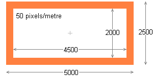 Each petal shell is an ellipsoid, which must enclose a cylinder 5 metres by 2½ metres. The frameworks of the shells are made of 250 by 50 millimetre wood. The enclosed space therefore has a clear height of 2 metres and a diameter of 4½ metres. Experiment has shown the optimum aspect ratio for the ellipsoid to be 2:1.
The 2:1 ellipsoid, which precisely envelops the cylinder, measures externally 7 by 3½ metres as shown below. The internal measurements of the elliptical ribs of the ellipsoid are 6½ by 3 metres.
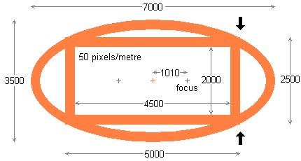 The doorways for the petal shells are on flat faces formed by slicing off the side of the ellipsoid in line with the two large black arrows as shown on the right. The flat face so produced is itself a 2:1 ellipse. The door is located in the centre of this elliptical face. There are 3 such sliced flat surfaces on each petal shell.
Not all of them will have an actual door. Some will simply be blank wall. It is along these flat surfaces that the petal shells mate with each other and with the central octagonal shell.
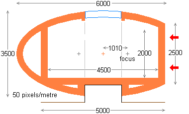 The flat elliptical frame for each doorway is 2½ metres high, allowing clear space for a door 2 metres high. The elliptical section ribs of the ellipsoid terminate at the top and bottom of the ellipsoid into a circular frame like the spokes of a wheel. Within the upper circular frame is a 1½ meter diameter round skylight. The lower circular frame is surrounded by vertical wooden ribbing to act as a receptacle for the 1½ metre diameter concrete support base. The floor beams meet in the centre and are bolted down to the concrete base. The internal floor of the petal shell is a measured metre above the outside ground level.
 On the right is a view of the elliptical door frame as it would be seen from the direction of the red arrows in the diagram above. The central vertical rectangle provides the clear space to fit a 2 by 1 metre door. Nowhere, however, does the doorway frame appear as a complete ellipse as shown on the right. Two of the frames (the side frames) of each petal shell are cut short at the black arrows. The third (centre) frame is cut short at both the black arrows and the blue arrows. Of course, when we construct the frames, we do not cut them like this as such: we never actually form the unwanted parts of the complete ellipse.
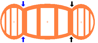 The 3 doorway frames of a petal shell are shown together on the left, viewed from a position directly in front of the central one. The two side frames slope away from the observer at 67½° from the plane of the screen. The corners between adjacent frames are in line between the pairs of opposing arrows. The total width of the 3 frames projected onto the plane of the screen is 6½ metres.
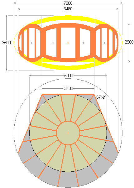 The three door frames are shown in brown on the right superimposed in their appropriate positions on a yellow outline of the whole ellipsoidal petal shell.
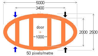
Below on the right is the corresponding plan view of the petal shell unit. The 16 semielliptical frame sections radially terminate short into circular centre frames at the top and bottom of the ellipsoidal envelope.
Only 6 of the semi elliptical frame sections form complete semi ellipses. Each of the other 10 frame sections is, to a greater or lesser extent, truncated where it meets one of the doorway frames.
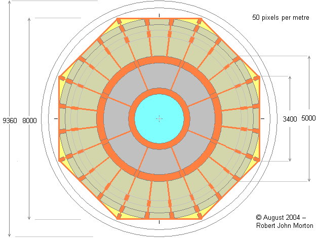
The 3400 millimetre flat elliptical edge at the top of the plan view mates with the central large shell. The flat side edges angled at 67½° to the line of the central edge mate with identical adjacent petal units.
The elliptical doorway frames of the central ellipsoidal shell must mate up exactly with the elliptical doorway frames of the ellipsoidal petal units. They must be identical in size and shape. Consequently, the dimensions already decided for the petal shells automatically determine the dimensions that must be used for the central shell.
This is an ellipsoid that must enclose a cylinder 8 metres by 2½ metres.
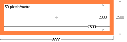 The framework of the central shell is also made of 250 by 50 mm wood. The enclosed space thus has a cleared internal height of 2 metres and a diameter of 7½ metres.
To preserve the 2:1 aspect ratio of its doorway frames, the central shell must also have an ellipsoidal aspect ratio of 2:1. The 2:1 ellipsoid that precisely envelops this cylindrical space measures externally 9360 by 4680 millimetres as shown below. The internal measurements of the elliptical ribs of the ellipsoid are 8860 by 4180 millimetres.
In the centre of the roof of this central shell is a round skylight 2 metres diameter. The central 4½-metre diameter section of the roof (that includes the skylight) is dropped 500 millimetres. This provides a ceiling height under the skylight of 2560 millimetres. The crater wall formed by dropping this central section of the roof allows a 250 millimetre high circular vertical window to be provided to give all-round natural lighting to the periphery of the room.
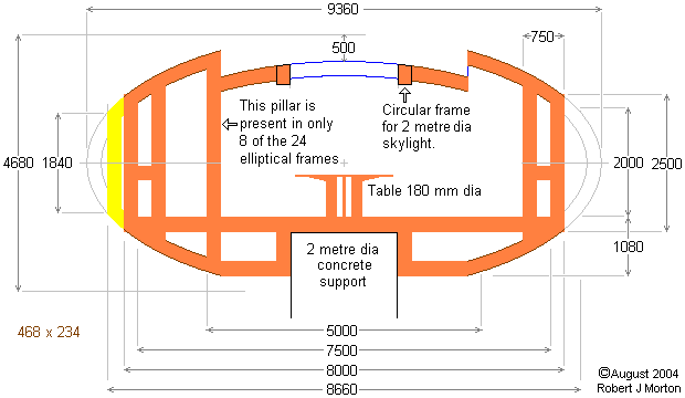
On the right of the above diagram, the height of 2000 millimetres is the clearance of the doorway and 2500 millimetres is the maximum top to bottom height of the doorway framework. This occurs at the mid-point of each flat of the octagon. On the left of the above diagram, 1840 millimetres is the top to bottom height of the doorframe at its extremity. This occurs at the corners between the adjacent sides of the octagon. This means that the above diagram is not a normal cross-sectional view of the ellipsoidal shell. The right half is a cross-sectional view where the horizontal is almost along the centre-line of a doorway. The left half is a cross-sectional view where the horizontal is in line with a corner of the octagon.
There are 24 semi-elliptical frames in the central shell. These semi-ellipses are not complete. They are all cut short to meet the circular frame at the top and bottom of the ellipsoid. In the top circular frame is the skylight. In the bottom circular frame fits the concrete support. The frames are also cut at the top of the ellipsoid to facilitate the lowering of the roof by 500 millimetres. Each semi-elliptical frame is given rigidity by an extra vertical beam, which gives an effective width to the vertical section of the frame of 750 millimetres. This depth is ideal for accommodating work-tops around the periphery of the ellipsoid. The 8 semi-elliptical frames that coincide with the corners of the octagon have 2 additional vertical supports. One in the corner of the octagon itself (shown in yellow above), and one whose outer edge is 5 metres from the centre of the ellipsoid. The latter supports (along with the 7 others) the lowered central section of the roof.
Beneath the diagram above, 8000 millimetres is the distance across the flats of the octagon, 8660 millimetres is the distance between opposite pairs of corners of the octagon. The following diagram shows the plan view of the central ellipsoidal shell corresponding to the above elevation view.
| Type of Frame Section | Quantity |
|---|---|
| 2-metre internal diameter circular frame | 3 |
| 4½ internal/5-metre external diameter circular frame segment † | 16 |
| Eliptical section 'spoke' for dropped roof | 8 |
| Vertical support for dropped roof | 8 |
† There are 2 circular frames: one around the edge of the dropped roof; the other around the top of the rim.
The outer skin of the central shell is made up of panels. Each panel incorporates its own section of the superstructure — like a unit-constructed body panel of a car.
| Type of Panel | Quantity |
|---|---|
| 2-metre diameter skylight | 1 |
| Dropped-roof segment | 16 |
| Outer-roof/corresponding-bottom segments | 48 |
| Corner-roof/corresponding-bottom fillers | 16 |
| Side-filler panels for each side of each door | 16 |
| Doors | 8 |
| Interlocking window segments for circular rim window | 24 |
| Outer floor segments | 24 |
| Inner floor segments | 8 |
| Centre floor segment (2-metres diameter) | 1 |
| Support for central lowered roof | 8 |
| Outer support panel | 24 |
| Corner extention support panel | 8 |
| Lower horizontal spokes | 8 |
| Lower vertical supports | 16 |
A separate frame structure makes it easier to replace panels. A panel may become damaged or it may need to be replaced by a specialised panel such as one containing a water jacket or solar array.
The frame structure should be the means of collecting rain water. These could possibly be internal gutters. Rainwater is then collected internally for flushing toilets. This means that panels with integrated frames can be butt-jointed together without the need for waterproof gasgets. The panels could be made of perforated metal sheet to collect rain water. This would also make it easier to form them into the ellipsoidal shape.
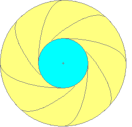 The central part of the roof is clad with super-tiles or panel sections that are shaped like the vanes of a camera's variable aperture system. The vanes are made of pressed metal (aluminium or stainless steel), carbon-plastic or fibre-glass. There is a downward fold along the clockwise edge of each panel and an upward fold along the anti-clockwise edge. Thus the clockwise edge is higher than the anticlockwise edge. This causes rain water to flow towards the concave anti-clockwise edge of each panel, creating a fast flow along this edge. This flow ends up tangential to the outer circumference of the roof, where it is received by down-pipes located at the 8 points along the circumference where each pair of panels meet. Each panel has necessary strengthening forms stuck or spot welded to its lower surface. These forms contain fixing points for fastening the panel to the wooden framework of the shell.
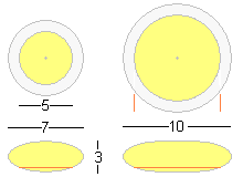 A separate circular ellipsoidal shell encloses each of the 18 circular rooms that make up the dwelling. There are two sizes of room. The 16 'petal' rooms have floors 5 metres diameter. These require shells 7 metres maximum diameter, whose vertical cross-sections are ellipses with major axes of 7 metres and minor axes of 3 metres. The two central rooms have floors 8 metres diameter. These require elliptical shells 10 metres diameter. The dimensions on the diagrams are in metres. Scale is 10 pixels per metre.
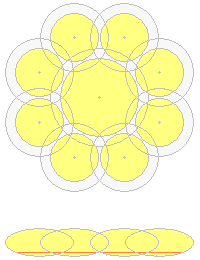 Ellipsoids fit together along a vertical flat surface to allow a common section of wall in which a door can be fitted. On the left is shown how 1 large and 8 small elipsoids fit together to form one of the modules.
The yellow circles are the floor areas. The larger white circle surrounding each yellow circle shows the maximum extent of the ellipsoidal envelopes. Where the white circles overlap is where slices of the respective ellipsoids must be removed to enable the ellipsoids to fit together.
Below the overlapping circles is an elevation view of how the un-sliced ellipsoids would overlap.
The ellipsoidal shells therefore have sections sliced off so that they can fit together. The way each of the 16 small ellipsoids must be sliced is shown below on the left. The shape of the cross section of each slice is a partial ellipse. The two side slices are the shape of an ellipse sliced off vertically at one end. The central slice is the shape of an ellipse sliced off vertically at both ends.
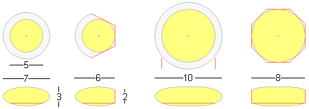
Above is shown the slicing for each of the two large ellipsoids. The slicing is on 8 sides. Each vertical flat surface of the slice is the shape of an ellipse sliced off at each end, and matches the centre of the three slices of each small ellipsoid.
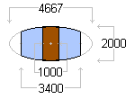 The dimensions of the entire dwelling are determined by the height of the doorways and the aspect ratio of the elliptical cross-section of the shells. The doors are 2 metres high and 1 metre wide. The ellipse embracing the door is therefore 2000 by 4667 millimetres. The octagon enclosing the 8 metre central room has a side of length 3400 millimetres. The doorway elliptical frame is therefore truncated to a width of 3400 millimetres as shown in the diagram on the right. The scale of this and the following diagrams is 20 pixels per metre.
 Eight of these truncated eliptical frames form the superstructure of the sides of the central room of the dwelling. The diagram on the left shows the elliptical frames that make up 3 of the sides of the octagon. One frame appears 'face-on', with its two adjacent frames angling away at 45°, so each appears to be contracted in its horizontal dimension to its actual length divided by the square root of 2.
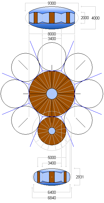 The next task is to fit an ellipsoidal envelope around this framework. The elipsoidal envelope must have an elliptical cross-section the same as that of the door frames, namely 7:3. The 8 metre diameter circular floor must be level with the bottom of the door frames. The only ellipsoid that will fit precisely is 9300 mm diameter by 4000 mm high. An elevation view of the octagonal central ellipsoid on the right shows the 3 visible door frames. The grey construction lines show how the features of the elevation view relate to the plan view of the central octagon of the daisy module below it.
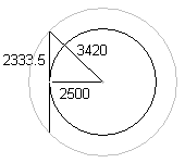
The ellipsoidal envelope of each petal (each peripheral room) must be sliced so that it presents a flat 4667 by 2000 mm elliptical door frame that matches exactly the corresponding elliptical door frame of one of the facets of the octagonal central room. This same ellipsoidal envelope must accommodate precisely the 5 metre diameter floor of the peripheral room. The 4667 by 2000 millimetres elliptical door frame is tangential to the 5 metre diameter floor, as illustrated in the diagram on the left. The radius of the enveloping ellipsoid must therefore be 3420 mm (larger grey circle).
 An elevation view of a petal unit is shown at the bottom on the right. It is shown projected from the 'bottom-most' petal unit on the daisy plan diagram on the right. With an aspect ratio of 7:3, the 'petal' ellipsoid must have a height of 6840 × 3 / 7 = 2931 mm. The view looks directly at the door frame that mates with the central octagonal unit, showing the adjacent door frames sloping back at 22½°.