Project
Introduction
Basic Requirements
Utility Independence
Activity-Based Design
Terrestrial Dwelling
A Landshare Home
Other Designs
The Search for Land
Victims of a Scam
Satellite Survey
A Virtual Model
Pilot Community
This is my basic design for a futuristic shell structure to accommodate the system of connected activity spaces described in the previous article. It forms a physical dwelling-cum-workplace designed to rest on any small reasonably flat area on the habitable surface of the planet.
Looking at a night-time map of the Earth, I see that all the illuminated areas hug very restricted parts of the habitable land of the planet. Certainly one main reason for this is that modern living demands that people cannot practically live beyond the reach of the utility grids that supply water, sewage, electricity, gas and telecommunications. I proposed to myself the idea that if I could design an accommodation unit that could supply all basic human utility needs independently of the grids, then this would open up vast areas of habitable land that are currently uninhabited. I called it a Universal Terrestrial Dwelling [UTD].
My UTD has internal independent means of acquiring its own air, water, electricity, heat and perhaps gas. It has its own drill and purification unit for acquiring water. Alternatively, it can catch rain water or extract it from the humidity of the air like a house leak or a bromelia plant does. It has an outer translucent surface below which is a coating of solar cells to produce electricity and heat. It also has openable ducts to small turbines for generating electricity by wind or breeze. It also has internal means of processing and recycling its own sewage and connecting to a universal global wireless communications network. It impinges upon the earth to only the minimum necessary and sufficient extent, with footings amounting to less than half a square metre. It is light and transportable; perhaps even vehicular.
It is made of a light durable material with high thermal impedance, something like Kevlar or the carbon fibre now used in aircraft construction. This is ideally formed from natural ingredients: something like carbon dioxide foamed papier mache made with a non-inflammable goo and reinforced with nets of strong organic fibres like the material of which spider threads are made. The shell of the dwelling, together with its internal walls and floors is formed in a giant mould or template.
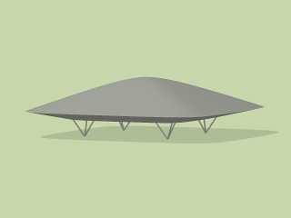 The shape of the UTD is streamlined in order to withstand the increasingly violent weather the world is now facing. I have experimented with many physical designs. The one I find most practical at the moment comprises a top section and a bottom section, each in the form of a square hyperboloid, with the vertical scale of the lower section being about 0·6 that of the upper section. A ray-trace simulation of this design is shown on the right. The illustration does not show its windows or other features.
The hyperboloidic underside of the UTD is truncated vertically so that just over half the area of the bottom of the UTD is flat. The UTD is suspended 2½ metres above the ground on 4 supports. Each support comprises 3 tubular struts which form an inverted tetrahedron with a foot at the apex. Each foot is only 15 cm radius, giving it a ground bearing area of only 0·07 of a square metre. The tetrahedral supports are retractable to facilitate transportation of the UTD.
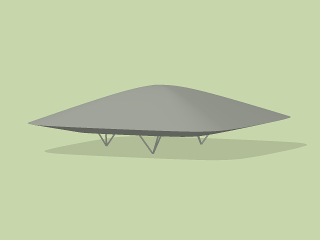 In an endeavour to minimise the UTD's impingement on the planet's surface, I experimented with the idea of using only 3 supports, as shown on the right. With only 3 supports, the UTD would be easier to level on an unprepared site. The UTD would, however, be less stable in high winds and the supports may need anchoring to the ground with penetrating augers. The 3 supports are positioned on the underside of the UTD such as to distribute the UTD's weight equally between the 3 supports.
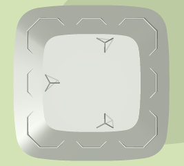 The illustration on the right shows the positioning of the 3 supports for 3-point contact with the ground. There is clearly a lot more over-hang than there is with 4 supports, which could result in greater instability. On the other hand, the 3-support configuration does lend itself to the possibility of attaching electrically-powered baloon wheels to form a tricycle undercarriage like that of an aircraft. This would allow the UTD to move slowly over land, so long as the land were not too uneven. This would enable the UTD to be self-positioning within a site but would leave it too unstable for long journeys.
 The internal space of the UTD is divided by walls arranged according to the pattern of octagons and squares shown on the left. This pattern is scaled so that it fits into the largest square that can be contained within the perimeter of the plan view of the UTD shell. The wall sections are all identical, measuring 3⅓ metres wide, 2¼ high and 15 cm thick. They are made of the same material as the outer shell. Some of them contain doors.
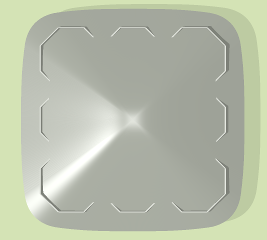 Notwithstanding, if all the wall sections were the full height, some of them would, in places, protrude upwards through the top of the UTD, as shown on the right. As can be seen, the roof level over about half of each corner octagon slopes downwards below the standard height of 2¼ metres. The lowest part of the roof at each far corner of each corner octagon descends to give a wall height of only 1598 mm. This is generally only a little below head height and so is still comfortably accessible. Such a height often occurs within the attics of conventional houses.
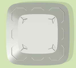 Full-height inner walls would also protrude downwards through the bottom of the UTD, as shown on the left. As can be seen, the floor level over about half of each corner octagon slopes upwards. This further shortens the standard wall height of 2¼ metres. The highest part of the floor at each far corner of each corner octagon ascends, thus cutting the wall height further so that it becomes only 1207 mm. The upward sloping floor could be seen as problematic. Nevertheless, this half-octagon of space lends itself well to certain excellent uses which I shall describe later.
Again as can be seen from the above two illustrations, the octagon in the middle of each side of the UTD does not really suffer much of a slicing effect from the descending roof line and ascending floor line. In fact, the sloping roof and floor only affects the first 1207 mm from the outer wall. This sloping part of the roof offers an ideal location for skylight windows which are low enough through which to get a horizontal view of the outside.
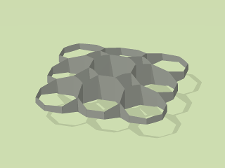 The inner walls of the UTD do not end at the standard ceiling height of 2¼ metres. They run all the way from the bottom to the top of the hyperboloidic shell, as shown on the right. The centre octagon, which contains the lift and stairs, is about 4·8 metres high, while the outer halves of the corner octagons are lower than the standard height, as previously described. The corner rooms are nonetheless quite spacious because they are more than the standard height towards the centre of the UTD.
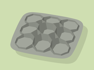 The view on the left shows the wall structure of the UTD complete with the lower half of the outer shell. Note how the floor curves upwards very slightly towards the edges of the peripheral octagons, especially the four corner ones. The four square rooms are lit by square almost-horizontal skylights in the upper shell. All the octagons are also lit by skylights. Most of these, however, are located in parts of the roof that are sufficiently inclined to allow a horizontal view of the surrounding land.
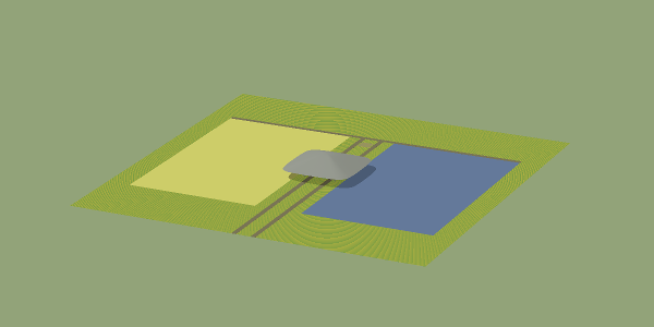
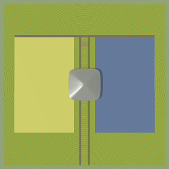 My Universal Terrestrial Dwelling can stand alone in any adequately sized plot of reasonably flat land. The plan view on the right shows the dwelling set within a two-hectare square of land in order to illustrate its size and scale relative to a standard landshare. Two parallel access driveways or footpaths join the UTD to the boundary of the plot. A perpendicular section of path forms the 'top' of the π shape to provide access to the inner part of the plot. The yellow area represents the proportion of the Earth that is currently cultivated to provide food. The blue area represents the corresponding area of fresh water.
Below is an aerial view, from an elevation of 20°, of the whole gleba with the UTD, lake and crop areas in the middle.
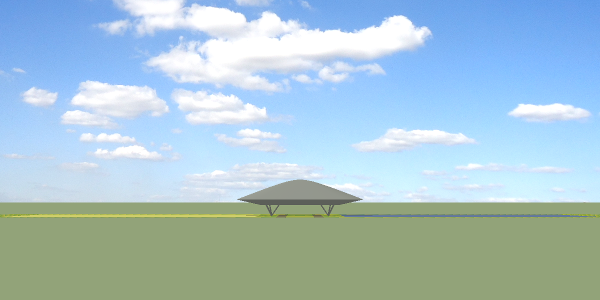
The following view is along the horizontal from a point at the mid height of the UTD. It shows the whole gleba looking along the access paths. The UTD's rounded hyperboloidic form gives it a pleasing æsthetic appearance and its aerodynamic shape vastly reduces its vulnerability to strong winds, hurricanes, typhoons and tornados.
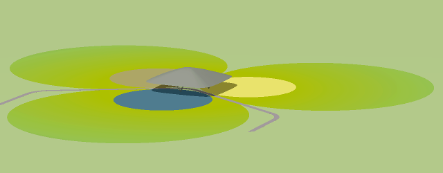
The 3-support version of the UTD does lend itself to the more creative setting of a gleba comprising 3 crop areas with a loop-type access driveway with the inbound and outbound sections 120° apart as shown below. This is the environmental setting used in the landshare home design described in the next essay.
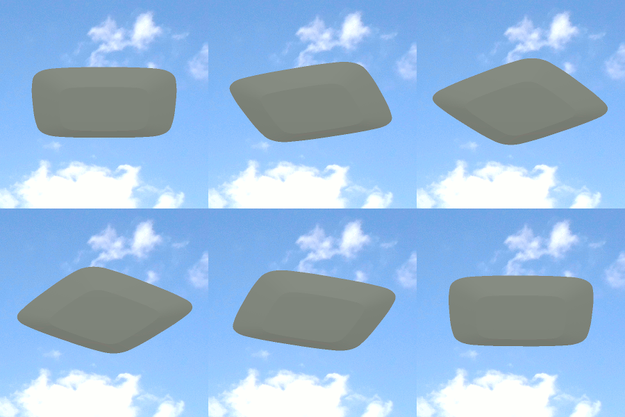 In a landshare-based society, there's a practical advantage — if not necessity — for being able to move to different landshare locations throughout one's lifetime. For this reason, I propose that, in this alternative world, homes should be essentially vehicular. They must be able to relocate easily. They don't need to move frequently. Nor do they need to travel at great speed. Preferably, such a home should, for the duration of a move, become some form of airborne vehicle that can move easily and safely under its own power and guidance, with the ability to avoid collisions with fixed obstacles and airborne objects. At least, it should be light enough to be transportable by helicopter.
Each of the spaces [9 octagons and 4 squares] within the UTD accommodates a specific activity or function as discussed in my previous essay on Activity-Based Design.
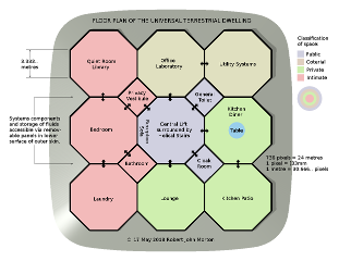 All these activity spaces, each labelled with its designated function, are illustrated on the right. The colouring of each space indicates its privacy classification. The central hexagon, containing the access lift and stairs, plus the square toilet room and cloak room, are classified as public space. This does not mean that the public at large are free to enter. It means that it is the space where I accept strangers and public officials who have reason to visit. It has a sofa, table and chairs for interview and discussion.
The office-cum-laboratory and utility systems octagons are classified as coterial space. This is space where I engage in economic and special interest activities. It is space where I would also invite members of my coterie: friends and colleagues who participate in my activities and share my special interests. The lounge, the kitchen-diner and the kitchen patio [shown in green in the diagram] are designated as private space. This is primarily family space where relatives and others are invited at the family's discretion. The bedroom, bathroom, laundry and quiet room [shown in pink in the diagram] are classed as intimate space.
The plan, as shown, is for a single person or a couple without young children. With young children, the quiet room is a divided area for the children's sleeping accommodation. In this case, the door between the parents' and children's bedroom areas is permanently shut and a door is provided between the privacy vestibule and the children's bedroom. Older children live in an adjacent UTD.
Following is my proposed design and content of each of the 13 rooms of the UTD. This is my personal preference. Notwithstanding, the design and choice of content for the 13 spaces is flexible. Others may prefer different designs and content. Please note that my particular choices of design and content reflect the intent that my UTD is essentially a research facility for developing the concept of a Universal Terrestrial Dwelling.
The dwelling is intended to have a minimum possible impact on the planet. For this reason, it impinges on the planet's surface in only 4 small circular areas, each about 0·7 square metre to a maximum depth of only 1 metre. The main floor of the dwelling is 2·8 metres above the surface of the planet.
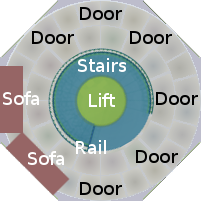 Access to the dwelling, from ground level, is via a 4 metre diameter retractable access tube, which descends from the centre of the underside of the UTD. This access tube contains a 2 metre diameter central circular lift surrounded by a helical staircase with carpeted 1-metre wide treads, which makes a 270° turn around the lift shaft. The octagonal entrance hall, at the top of the stairs, has doors in 6 of its walls to access the rest of the dwelling. The other two walls are occupied by comfortable sofas with wide hardwood arms, which can be used for resting documents and for writing.
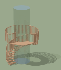 A view of the lift-shaft and its encircling staircase is shown on the right. It is shown in complete isolation from the entrance hall module in which it is installed. Thus, the annular upper floor of the entrance hall, which surrounds the staircase, is not shown. The lift-shaft cylinder is shown in a transparent material. This is really just to make visible the path of the stairs as they pass behind the lift-shaft. Nonetheless, it could be a valid material for the lift-shaft. The staircase itself is illustrated in wood, although other suitable materials could be used. The staircase is viewed, in this illustration, from the direction of the cloakroom on the upper landing area.
The lift and staircase retract upwards and a horizontal circular door closes the opening to the outside in the bottom of the UTD. This renders the UTD secure from unwanted access from the outside when necessary.
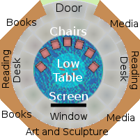 A plan of the dwelling's lounge is shown on the left. In the centre is a 4-metre diameter round carpet upon which is placed a 2-metre diameter low glass table. At the edge of the carpet, tangential to it, is a 2-metre wide television screen. Easy chairs are arranged around the table for viewing the screen. Shelves, containing books and other media, with a reading desk in the middle, occupies a 135° peripheral arc on each side. There is a low plinth behind the screen, upon which solid art-forms are stood for display. Behind the chairs is a semicircular glass wall to protect the chairs from the doorway.
People today spend a lot of time viewing video programs. It is one of the main activities in most households. Our landshare dwelling must therefore include a room specifically designed for, and dedicated to, watching visual content. The UTD is also a workplace. A workplace in a high technology age needs a room where people can sit to view an audio visual demonstration or hold a group discussion.
The ideal environment and equipment for recreational video viewing are essentially the same as for audio visual demonstrations for work purposes. Since the two activities take place at different times of the day, the same place can be used for both. The best way to view something together as a small group is to sit in a semicircle. The screen is flat, so those in the middle of the group will get a more direct view of the screen than those at the ends. We need to make it fairer.
 Consider a dipole radio antenna. It radiates power in a way that delivers equal signal strength to all points on a circle that touches the middle of the dipole. A dipole is by no means a perfect analogy for viewing a screen, but it is better than nothing. For each person to receive equal illumination from the screen, they must sit around a circle that touches the centre of the screen. An individual's view would however be too oblique if he sat anywhere on the half of the circle closest to the screen. Everybody must therefore sit on the semicircle furthest from the screen, as illustrated on the right.
Each chair is a comfortable well upholstered easy chair in leather or soft fabric. The centre point of each seat rests on the semicircle. The chairs swivel easily to enable people to sit with equal comfort while facing either the screen for viewing or the centre of the group for discussing.
Centred within the 4-metre diameter carpeted circle is a low round glass table 2 metres diameter and 46 centimetres high. At the far edge of the round carpet is the screen. This is essentially a very large tablet computer with internal mass storage for audio, video and documentary content. It is controlled via a standard keyboard and mouse on the low glass table, which are linked to the screen via Bluetooth-type radio. The screen receives content via the dwelling's local area network.
 The best size for a high definition screen for viewing by a group of up to 8 people is between 1½ and 2 metres wide with an aspect ratio of 16:9. The screen is mounted on 100 millimetre metal box rails, which span from floor to ceiling. The height of the screen is adjusted so that the middle of the screen is 1040 millimetres above the floor, the ideal viewing height from an easy chair.
The sound system comprises 4 speakers plus a sub woofer. A right and left speaker is mounted in the ceiling above each side of the screen. Two more speakers are mounted one in each end of the peripheral library arc behind the chairs. The sub-woofer is mounted in the floor underneath the table.
 The library and the media viewing facilities are both in the lounge area. It is therefore possible, at times, that sound from the viewing equipment could seriously disturb people who are reading. At such times, anybody using the video facilities can turn off the universal sound system and use headphones. These should be cordless, using Bluetooth-type technology to receive the media sound via short-range radio broadcast.
Dimmable shielded coloured strip LEDs are mounted in recessed grooves around the edge of the screen enclosure to provide background lighting for viewing.
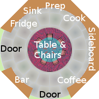 On the left is the physical plan of the Kitchen-Diner module. The focus of the Kitchen-Diner is the 2 metre diameter round table placed and fixed at the centre of the room. It is shown with 7 chairs. However, there is plenty of space for as many as 12 chairs around this table. The centre of the table is rotatable to facilitate easy access to condiments and serving dishes, which stand on small electric hobs. Directly above the table is the room's 3 metre diameter round skylight. This is ringed by small spotlights for evening. The table and chairs stand on a 6 metre diameter deep-pile carpet.
 The adjacent diagram models the flow of the processes of preparing a meal, eating it and washing up afterwards. The meal's ingredients are taken from the food store (1). The cooking utensils are taken from the pan store (2). The ingredients are washed and prepared (3). Peelings and other waste are discarded (4). The prepared ingredients are put in pans, which are placed on the stove (5). The table is set with plates, cutlery and other tableware (6). The meal is served and eaten (7). After the meal, the dirty dishes, cutlery and serving pans are cleared from the table (8). Waste is cleared from the plates and pans (9) after which they are washed (10) and put in their respective storage units (11) and (12). These processes are accommodated in the physical context of the illustration above.
The main active appliances used in these processes are a cooker and a dish washer. A freezer and refrigerator are also available for food storage. The cooker comprises a 2-ring ceramic hob and a separate conventional oven. It may also include a 'microwave' or HF oven. An electric mixer or blender may be useful but is not really necessary. I also like to have a toaster. Ideally, two sinks are required. A normal sink is needed for washing large cooking utensils. A smaller sink is useful for washing ingredients when preparing a meal.
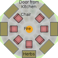 The kitchen patio contains 7 peripheral herb boxes for growing kitchen herbs and protective flowers. These are shown in green in the adjacent illustration. In the centre of the kitchen patio is a small floor-level fire. It has ceramic logs and is fired by gas. It has a chimney vented via the roof above. In an arc around the fire are 7 chairs. These could ideally be ground-level squatting chairs. The lower right half of the kitchen patio has a lowering ceiling and ascending floor. It thus provides only sufficient height for sitting. Above each chair and the vacant entry space is a round skylight window.
It is here that we can sit as if around an ancient aboriginal counsel fire, whose flames can be seem weaving their erotic dance upon their stage of glowing embers, exuding benign powers that inspire the mind and soothe the soul. It is a place that fires the imagination, where we can sit and contemplate, and philosophize endlessly about relationship, society, economics, life and the universe.
 The bedroom is spacious with private access to the other parts of the dwelling by way of a 3·33-metre square vestibule. Surrounding the central circular area are two built-in units, The one behind the bed is simply a wardrobe. The other, which is 3 times the size, accommodates a central dressing table flanked by two wardrobes. Natural light for the bedroom is from a sloping skylight, which is somewhat set back from the dressing table. From the bed, this offers a clear view of the night sky. Other doors give access to the Quiet Room, the en suite Bathroom and the Laundry Room.
 The cycle of processes, which the bedroom is intended to host, is illustrated on the left. These processes do not, of course, always follow the complete sequence. Indeed, a process may occur more than once in the cycle. For example, one would perhaps want to wash before and after coitus. Between dressing and undressing are all the activities of the day that take place outside the bedroom. This bedroom is designed to provide, in an optimum environment, all the facilities necessary for these 5 closely coupled processes of daily life.
The base of the bed is made as a grid of 2 cm wide by 5 cm deep pine slats with 2 cm spacing between slats. The entire grid is a 2 metre square, with a 30 cm square cut out from each corner to give the bed the shape of a Maltese cross. The grid is surrounded by a pine flange 15 cm wide. The flange is finished in under-padded dyed leather. The flange is angled at 60° to act as a retainer for bedding and pillows. The pine grid is supported on top of a pine plinth, which could contain large drawers for storing spare bedding.
Upon the pine grid is placed a very thick 2 metre by 2 metre feather mattress, again with 30 cm squares cut from the corners. It is quilted to form separate feather filled compartments so that the feathers do not gather into large humps. The mattress is encased in a thick patterned velvet over-casing that can be changed and washed. The over-bedding is a 170 cm by 170 cm covered duvet, with a 30 cm square cut from one corner. The duvet is of a weight appropriate to the season and is used with 4 matching covered pillows.
Instead of a headboard and bedside tables, the bed has a bed-height table of glass or wood 140 cm by 40 cm at its head for things that must be reachable from the bed, such as a carafe of drinking water and glasses, and an electrically warmed chalice of massage oil.
 For sleeping, both the occupants lie with their heads on Pillows 1 & 2 next to the glass table. The duvet covers the occupants symmetrically, overlapping Pillows 3 & 4. For coitus in the Tantric-T position, the man lies across the bed with his head on Pillow 3, while the woman moves to the centre of the bed with her head between Pillows 1 & 2. She may choose to pull one of the pillows to be directly under her head, but having her head low between the pillows should afford her a better stance. The advantage of copulating in this sideways position is that neither participant puts weight or unproductive physical pressure upon the other. Pillows 3 & 4 can be placed on the other side of the bed, and the duvet turned over, to provide a mirror configuration if this is preferred.
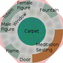 A floor plan of the Quiet Room is shown on the left. As with all the other rooms of this dwelling, the entire circular floor is covered in specially shaped cork tiles coloured to look like light grey stone. The only entrance is from the bedroom. In the centre of the room is a 6 metre diameter lawn textured carpet. The focus of the Quiet Room is a raised plinth spanning a 90° arc. In the centre of the reduced vertical space of this arc is mounted an inspirational crystal totem. On the plinth, flanking the crystal totem, are two large abstract wood carvings. One is male; the other female.
Either side of the plinth, diametrically opposite each other are a vortex flame unit and a water fountain unit, each enclosed in a floor-to-ceiling glass cylinder. The 90° arc diametrically opposite to the totem and sculptured figures, contains a continuous upholstered seat. This is where people may sit and meditate or simply relax and think.
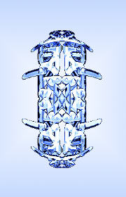 The focus of the Quiet Room is a raised plinth spanning the 90° arc between the two passage entrances. In the centre of the vertical wall of this arc is mounted a crystal totem as shown on the right.
The totem does not represent any deity. It is simply a focus for the mind. As such it could represent one's inner self or, perhaps even more profoundly, the relationship between two human inner selves.
The totem is also the Quiet Room's main luminary. For this purpose, it could have in-studded Light-Emitting Diodes (LEDs), or — better still — it could itself be a single enormous LED.
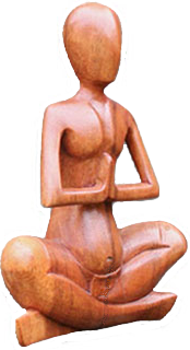 On the plinth, flanking the crystal totem, are two large abstract wood carvings like the one shown on the left. One is male; the other female. Perhaps the totem depicts the relationship between the inner selves of the male and female figures and therefore, by inference, that also between the human couple who inhabit the dwelling.
![]() On the left of the door, when entering the Quiet Room, is a flame device. It is in a glass tube, which is vented to the outside top and bottom. This generates a gentle flickering vortex flame extending about a metre. This flame creates an ambience of tranquillity within the room. It can be switched on or off, just like an electric light, from a wall switch at the entrances to the room. The fuel for the flame is some form of organic oil, which is kept in a tank below the floor. At the opposite side of the room from the flame unit is a small water fountain.
On the left of the door, when entering the Quiet Room, is a flame device. It is in a glass tube, which is vented to the outside top and bottom. This generates a gentle flickering vortex flame extending about a metre. This flame creates an ambience of tranquillity within the room. It can be switched on or off, just like an electric light, from a wall switch at the entrances to the room. The fuel for the flame is some form of organic oil, which is kept in a tank below the floor. At the opposite side of the room from the flame unit is a small water fountain.
The Quiet Room itself extends to the full height of the shell. Natural lighting for the Quiet Room is thus provided by the full upper extent of the shell's skylight windows. At night, dedicated external spot lights illuminate the sculptures. Glass sculptures and abstracts could be additionally lit artificially from within.
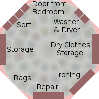 Dirty clothes are placed into bins located on the left of the door from the bedroom. Each bin is for clothes requiring a particular washing machine program. The bins are mounted on casters so they can be moved easily. The clothes are taken from the bins to the washing machine located on the right of the door from the bedroom. Next to the washing machine is a dryer. However, there is also hanging space in the centre of the laundry room. After drying, clothes are placed in the dry clothes storage unit. Any that are seen to need repair are passed to the repair bench, which includes a sewing machine and manual sewing requisites.
Here, clothes are repaired and then passed back to the dry clothes storage unit. Clothes that are deemed to be beyond repair are thrown in the rags storage on the other side of the repair bench. The storage unit on the left of the laundry room is for soap, cleaning products and maintenance requisites.
Laundry once was quite an involved operation requiring outside resources. It was conducted on at least the scale of an entire household. In many cultures it was done on a communal scale and was an active conduit of social contact. However, the modern automatic washing machine has made it possible to bring the clothes washing process close to its primary input/output — namely, the bedroom where people change their dirty clothes for clean ones.
 The general system flow model of the laundry process is shown on the left. In the bedroom, people change between their day clothes and their night clothes. When clothes become dirty, they are placed in the dirty linen bins in the laundry room. Clean clothes are taken back from the laundry room, where they are placed in the drawers and cupboards of the wardrobes, ready to be worn. New clothes are introduced into the cycle when required. Old warn-out clothes never return after being sent for washing. They are purged from the cycle during the repair process. In the laundry room, the pre-sorted dirty clothes are put in the washing machine set to the program corresponding to the bin from which they were taken.
After washing, the clothes are hung on drying rails in the laundry room, which has a large openable skylight to aid the flow of air when weather permits. Extra drying is done by a drying machine when hanging space is insufficient or when the natural humidity is excessive. Some clothes at this stage may need to be ironed or pressed. The clean dry clothes are then put in the clean clothes cupboard ready to be transferred back to the bedroom. There they are put in the wardrobes to air. The bedroom wardrobes are equipped with warm air circulation so that even freshly washed clothes can be placed there to air until they are needed for wearing.
Clean clothes needing repair are diverted to a sewing work station before being returned to the bedroom. Clothes found to be beyond repair are placed in the rag bin to be used as cleaning rags.
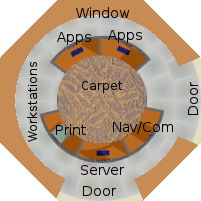 The dwelling's work space is shown on the right. The curved wall unit, stretching the long way round between the two doors, provides desk space and a work bench with overhead and underneath storage for books, stationery, tools and equipment. The curved wall unit, stretching the short way between the two doors, is a floor to ceiling book case. In the centre of the work space is a console containing five work stations used for computing, communications and navigation. The door at the bottom provides access from the central hall. The door on the right provides the only access to the Utility Systems room.
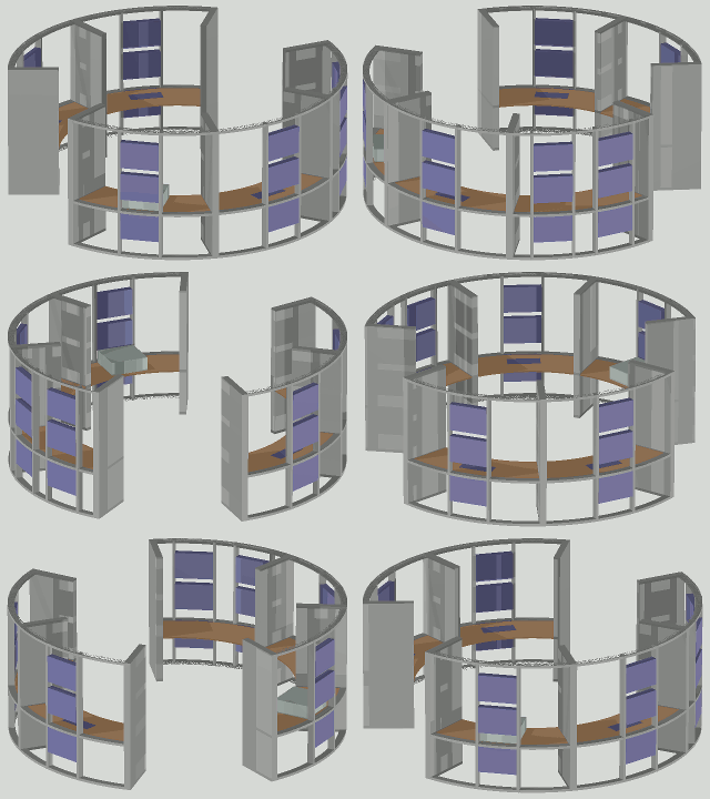 The work space's 7-segment central console is shown on the left. It is rotating in order to show details of its 5 equipped segments. Three of these are computer work stations. One of the remaining 2 is a printing and scanning station. Another is a communications and navigation station. Each equipped segment has a pair of standard 23-inch rack rails at the rear, between which up to 3 standard flat-format 23-inch equipment cabinets may be mounted. Two of the 7 segments are unequipped to allow access.
The outer radius of the console is 2½ metres. The desk sectors are 75 cm deep. This leaves the inner circle of the console with a radius of 1·75 metres to give adequate space for chairs and personal access.
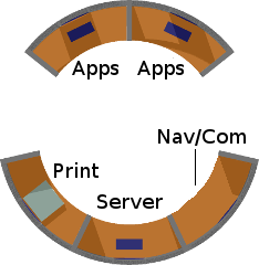 On the right is a plan view of the console, which is oriented to be consistent with the plan view of the whole work space octagon shown above. The two computer segments that are next to each other are straight-forward PC workstations. They have access to the console's local-area network and may be switched off when not in use. The segment diametrically opposite these two is also a computer station. However, this computer hosts various servers. It is therefore kept running all the time. This computer also acts as the dwelling's router, which provides access to the outside world. This segment is flanked by the print scan station and the navigation & communications station.
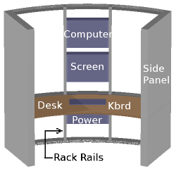 The view on the left shows one of the two normal computer stations. A monitor screen is mounted on the central rack-rails of each station. The height of each screen can be adjusted independently to suit each human user. Each station's computer is housed in a standard flat-format 23-inch cabinet set above the screen. The cabinet shown below desk level houses a battery back-up power supply and cooling system for the screen and computer. The keyboard and mouse are placed on the table in front of the screen.
A loudspeaker is fixed to each rack-rail just above the screen to provide local sound. Additionally, each computer workstation has a headset (headphones with a boom microphone) for private listening and voice communication. This normally hangs on a hook fixed to the side of the vertical divider panel at the left of the workstation's desk area. Headset cables are normally connected to the left earpiece.
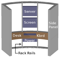 Diametrically opposite the above pair of PC work stations is the server/router station shown on the right. Although it can also be used as a general purpose PC work station, the server+router station's main roles are as follows: 1) running on-line servers such as web, FTP, eMule, gnutella and G2, 2) running a local area network (LAN) router serving the other two workstations and the printer scanner station and 3) running an infrastructure router which acts as a 3-way junction in our Landshare World's global network. For this reason it is generally kept running continuously.
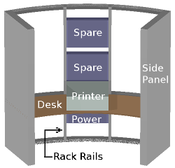 On the right of the server/router station is the printer/scanner station as shown on the left. I can never decide whether I prefer a separate printer and scanner or a device which incorporates both. Both options have their different merits. On the left, it is a combined unit that is shown in the middle of the segment's desk space. Its printing and scanning services are made available to the work stations via the local area network. Stationery and consumables for the printer and scanner are stored within the confines of the segment.
There is plenty of room around the circular corridor outside the console to access the rear of each flat-format computer cabinet for maintaining and upgrading the equipment. All power and signal cables are channelled neatly within a cable gully along the outer circumference of the desk surface. From there, they run up the insides of the hollow rack rails to the equipment cabinets. Cooling fans from all equipment cases have a clear exhaust path into the large peripheral corridor around the console.
The dwelling's means of navigating and of communicating with the world are accommodated within the Nav/Com segment of the console. Uniquely, this segment has two sets of vertical rack rails: one for navigation equipment and one for communications equipment.
In Landshare World, there is a communications infrastructure, which fulfils the role currently fulfilled by the Internet. It is not, however, safe or expedient for landshare dwellers to be dependent upon the services or subjected to the ulterior motives of corporate or State interests. The Landshare Internet is therefore based on a distributed millimetric radio network in which each dwelling is an active node.
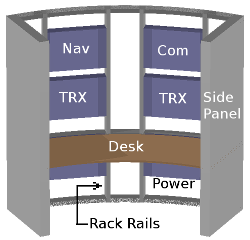 For this purpose, 3 radio-frequency (RF) modems are housed in the upper right-hand cabinet of the comms segment. Each of these highly sophisticated and configurable modems is connected by a LAN cable to a router socket on the server/router computer. The co-axial input and output of each modem are connected to each of 3 millimetric radio transceivers in the same cabinet. These in turn are connected to dish aerials mounted in the roof of the work space octagon.
Each of the three millimetric transceivers forms one end of a point-to-point communications link between this Landshare dwelling and one of three neighbouring Landshare dwellings. Thus is formed a worldwide wireless network of low vulnerability. Its much larger number of nodes makes it somewhat slower than the present-day Internet. Notwithstanding, its lack of speed is well overcome by adopting a different paradigm for distributing information.
The high bandwidth communication, provided by this Landshare "Internet", is not always necessary. But direct ultra-reliable low bandwidth communication, which the Landshare "Internet" cannot provide, sometimes is, especially in emergencies. For this reason, the communications segment also contains low, medium, high frequency and VHF transceivers, which exploit the facilities nature provides for infrastructure-independent communication.
For this purpose, the communications segment also contains communications equipment covering the long wave (low frequency), medium wave (medium frequency), short wave (high frequency) and VHF. Included in the cabinets are front-ends and converters reaching up to 2 gigahertz.
To be able to transmit and receive radio signals effectively, these equipments must be coupled to the universe via appropriate forms of electromagnetic transducers. Depending on the part of the radio spectrum concerned, these transducers can be variously aerial wires, rod antennas, magnetic loops, dipole-fed multi-element arrays and waveguide-fed dishes, plus other exotic concoctions.
Rod antennas of various sizes are built into the space above the ceiling of the work space octagon. These extend upwards through the roof above and can be retracted by motors, which also close the roof opening during storms. Magnetic loops of a broad range of sizes are built into the fabric of the dwelling. Dish and array antennas are also accommodated in the space above the ceiling of the work space octagon.
The Earth's Ionosphere offers a more direct and infrastructure-free means of communication. It can, however, be a fickle friend. Long-range communication paths open and close arbitrarily at different frequencies. Finding the optimum working frequency between two locations — at different times of the day, year and solar cycle — requires much knowledge, skill and patience.

For this reason, HF communication has a permanent element of on-going research. Hence research is also a function of the communications segment. To maintain a reliable channel, it is generally necessary to use multiple-diversity links. That is, having equipment working on more than one frequency at a time, so that, when one or more channels fade out, at least one other is still open.
Research also continues into different ways of using the short wave spectrum, such as sharing the space via a chip-coded spread spectrum regime to offer both reliability and privacy. And underpinning all is an on-going programme of research into the electric and magnetic aspects of the Earth's atmosphere, and indeed, of the universe beyond.
Landshare society is semi-nomadic. For this reason, the dwelling is vehicular — or, at least, transportable. It is able to move — or be moved — from one location to another. For this it needs a means of navigation and flight control.
A diversity of active conventional means of navigation are installed in the so far unused tower units in the vertical side cabinets of the central console. These include a compass, sextant, inertial platforms, radio aids and GPS. They also include research devices for new experimental means of navigation such as neural network based landscape recognition, geo-sonic resonance, pulsar signature recognition and automatic optical star fixing. The aim of these new experimental methods is to make dwelling navigation as independent as possible of artificial infrastructure. Some of these tower units also contain devices for invoking and controlling the dwelling's motive power.
This is what makes the UTD independent of utility grids like piped water, ducted sewage and gas/electricity supply grids. Telecommunications and navigation facilities are based in the office/laboratory work space octagon.
 The acquisition, purification and re-cycling of water and the production of gas and electricity all, by nature, require distributed systems. Consequently, these processes are distributed throughout the UTD. The consoles in the utility systems room, shown on the left, contain only the controls and certain key processing units. The water console handles the drilling for artesian water, the extraction of water from air and the capture of rain water. The centre of the 3 consoles handles the heavy metals testing and purification of freshly acquired water. The water is purified by firstly passing it through charcoal or ceramic micro-filters.
Then it is oxygenated and irradiated by ultra-violet rays, preferably from sun light. The water is then ready for human consumption and washing. The re-cycling console controls the processing of sewage into flushing water. Where location and climate allow, re-cycling is done by biological means external to the UTD. In a tropical climate, it is done preferably by banana trees. In a temperate climate where banana trees can't survive, this process must be done via a reed bed. In difficult locations, the re-cycling has to be done artificially in active tanks within the body of the UTD.
The two consoles at the top right of the above illustration control the acquisitions of electricity and gas. There are several options for generating electricity, including solar cell panels in the translucent surface of the roof of the UTD, wind turbines powered by breeze entering ducts on the underside of the UTD, bio-diesel and other heat engines such as the Sterling. An option for a gas supply is bottled propane but this is not preferred. A natural option such as biomass is more the intent.
The reason for the substantial control consoles in the utility systems room is that the UTD is essentially a research project. Consequently, it is the firm intention that all parameters of all systems should be monitored and documented and contributed to a central knowledge base as a resource for future design.
Custom designed user-maintainable deep-cycle cells for electricity storage, plus chargers and inverters for providing the variety of supply busses used throughout the dwelling, are distributed around the available space between the UTD's rooms and its outer skin. These are accessible from outside the UTD via removable covers in the underside of the outer skin. The cells contains a reserve sufficient to meet the UTD's full electricity demand at night and during periods with little sunshine or wind.
Within the dedicated laboratory space, around the periphery of the utility systems room, the residents monitor and control the general operation of their dwelling and gleba. Herein also they do special projects that are of particular interest to them. Such projects are of two types:
those that are essential and common to all landshare-based dwellings and
those that are of specific interest to the particular occupiers of this dwelling.
The first type includes monitoring and control units for all the essential systems and services within the dwelling such as electrical power and lighting, heating and cooling, air circulation and filtering, vacuum services, water and waste, sound and communications, and surveillance.
 The first type also includes apparatus for monitoring a multiplicity of parameters fed from sensors throughout the gleba. Among these are devices for monitoring and analysing natural resources, climate and crop health both in the field and in storage. Software is used for analysing raw data. For example, a neural network program is used to analyse the spectrum of reflected light from a crop to determine its condition and readiness for harvesting. Software is also used for analysing soil and climate to determine the best crop mixes and rotations for the particular gleba.
Particular instances of the second type of project depend on the personal interests of the residents. I would like to work on the development of a fractal architecture for a global communications network that would link all landshare-based dwellings seamlessly, rendering them immune from State and corporate invasion of personal peace and privacy.
This gleba-based dwelling is designed to be self-sufficient in maintenance and repair. Its occupiers therefore need to be equipped to keep the shell and all its systems in good repair and working order without any help from outside services. Some of the peripheral work space contains a work station with a particular speciality. Examples of different possible specialities are:
This workshop is thus equipped to maintain and repair (and possibly construct) all types of items and devices used within the farmlet. These would include:
This peripheral work space includes new forms of machine tools made of triangulated tubing of light metal alloys or strong composite materials, with mild or tool quality steel being used only for tools and hardened work surfaces. This work space should perhaps be the first space in the UTD shell to be equipped. Its facilities could then be fully utilised in the construction of the other spaces and infrastructures of the UTD.
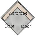 This 3⅓ by 3⅓ metre room provides private access to the intimate part of the UTD, namely, the bedroom and the ancillary rooms that adjoin it. Privacy is enhanced by the fact that the door from the main hall and the door into the bedroom itself are at right-angles to each other, discouraging a direct line of view from the hall to the bedroom. The vestibule contains a built-in wardrobe along the other two adjacent walls for such things as dressing gowns.
 This is for use by day visitors. There are no overnight visitors to the UTD, since there is only one bedroom. Nevertheless, the general toilet does provide all the facilities of a bathroom to avoid any need or excuse for a visitor to use the private bathroom. Note that the shower, toilet and wash basin are all along the same wall, which backs onto the wall of the kitchen where the sink is located, thus minimizing the water and sewage piping necessary.
 This provides the same full bathroom facilities directly to the bedroom. Note that the shower, toilet and wash basin are all along the same wall, which backs onto the wall of the laundry room where the washing and drying machines are located, thus again minimizing the water and sewage piping necessary. Along the opposite wall is a copious floor-to-ceiling storage cupboard for a long-term supply of bathroom requisites.
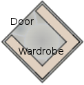 This opens directly into the entrance hall. It is, for the most part, for use by day visitors. It has full built-in wardrobes along 3 walls and provides adequate space for the storage of coats, shoes, boots and special out-door requisites for cold climates. It can also contain indoor moccasins for use by guests. The cloak room is accessible directly from the top of the helical staircase, and is also directly opposite the exit door of the lift.
Machines and active units of the UTD's utility systems are distributed around the UTD in order to distribute weight. Only the control units and administration are located in the Utility Systems octagon.
All 3-dimensional views of the farmlet and UTD in this article were generated using POV-Ray 3.6 from POVray scripts written by me. See the relevant povray script file for details. All other illustrations were created using GIMP. Over many years I have played around with many other designs for the farmlet dwelling. Notwithstanding, the one I have described herein is, to my mind, the most practical and endearing.